Since the earliest days of the automobile, the spark plug has been an autonomous system capable of initiating combustion in the chamber with great flexibility. However, it has now reached its limits in gasoline engines, to the detriment of efficiency.
Valvijet turns TJI into a system as adaptable, self-contained, stable, and flexible as a spark plug, while delivering ignition power, spatial distribution, and turbulent dynamics that open up new possibilities - well understood in principle, but impossible to apply until now.
For practical and opportunity-driven reasons, Valvijet has been studied since 2018 on modified Diesel engines (image below). The transfer to gasoline engines is straightforward, requiring only a slightly different pre-chamber insert:
The Valvijet technology package relies on four main functions:
Prototypes of all components performing these functions are operational, except for the compressor, whose bench testing will begin in early 2026, with no identified risk of failure:

With this package, Valvijet removes all functional barriers to turbulent jet ignition:
With Valvijet, turbulent-jet ignition becomes as stable and reliable as a spark plug. The initial conditions in the pre-chamber are guaranteed at the start of every cycle and no longer depend on the main charge nor on the previous cycle:
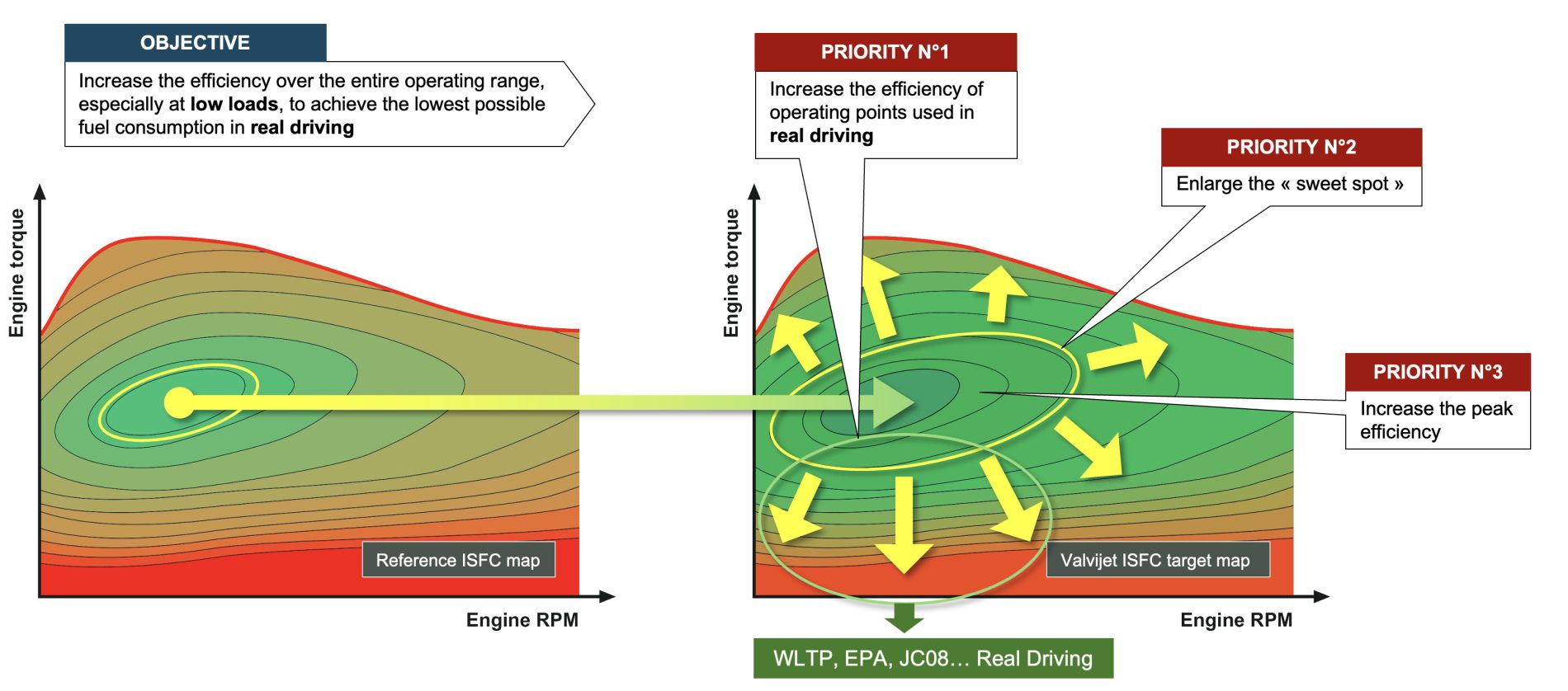
Valvijet’s goal is not to achieve the absolute highest peak efficiency at all costs. Claiming such a result is only meaningful if average fuel consumption is reduced across the entire operating range - particularly in the areas where the engine operates during homologation cycles and in real driving conditions.
The aim of Valvijet is to enable inherently fuel-efficient engines using a relatively “standard” technology mix (PFI, TJI, turbocharging, VVT). The challenge is to limit the need for heavy hybridization with equivalent CO₂ emissions, thereby reducing vehicle cost:
This component is operational on the engine test bench.
The Valvijet mixer centralizes the preparation of the pilot charge: only one mixer per vehicle. A single mixer can be shared across a wide range of vehicles and can, for example, equip any engine with a power output between 40 and 200 kW. This level of standardization promotes high reliability at low cost.
When the vehicle starts, the Valvijet mixer becomes operational in about one second.
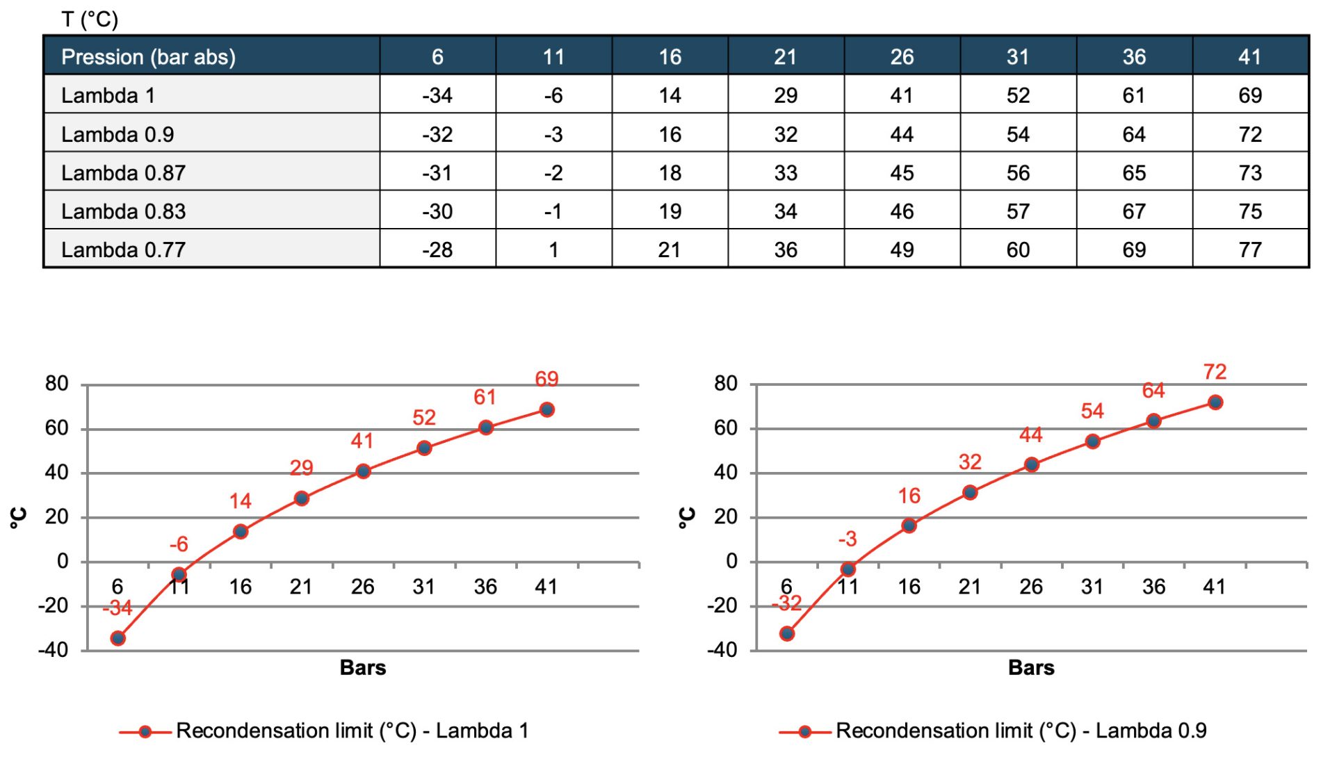
The pressure inside the mixer is controlled by the Valvijet compressor to prevent any re-condensation - even partial - of the gasoline, regardless of temperature or air/fuel ratio. During startup, the pressure increase in the mixer follows the rise in engine temperature. This ensures the complete absence of condensation in the line connecting the mixer’s blending chamber to the pre-chamber.
The table below shows the maximum permissible pressure as a function of temperature. For example, at −6 °C, the pressure in the mixer must not exceed 11 bar to maintain a 100% gaseous mixture at λ = 1. Under these conditions, and thanks to the Valvijet check valve, the engine’s BMEP is limited to around 12 bars for a few seconds - which is necessary for engine durability. As soon as the circuit reaches 30 °C, the engine can deliver full torque and full power. From 56 °C onward, the system enables full deployment of all fuel-consumption-reduction strategies:
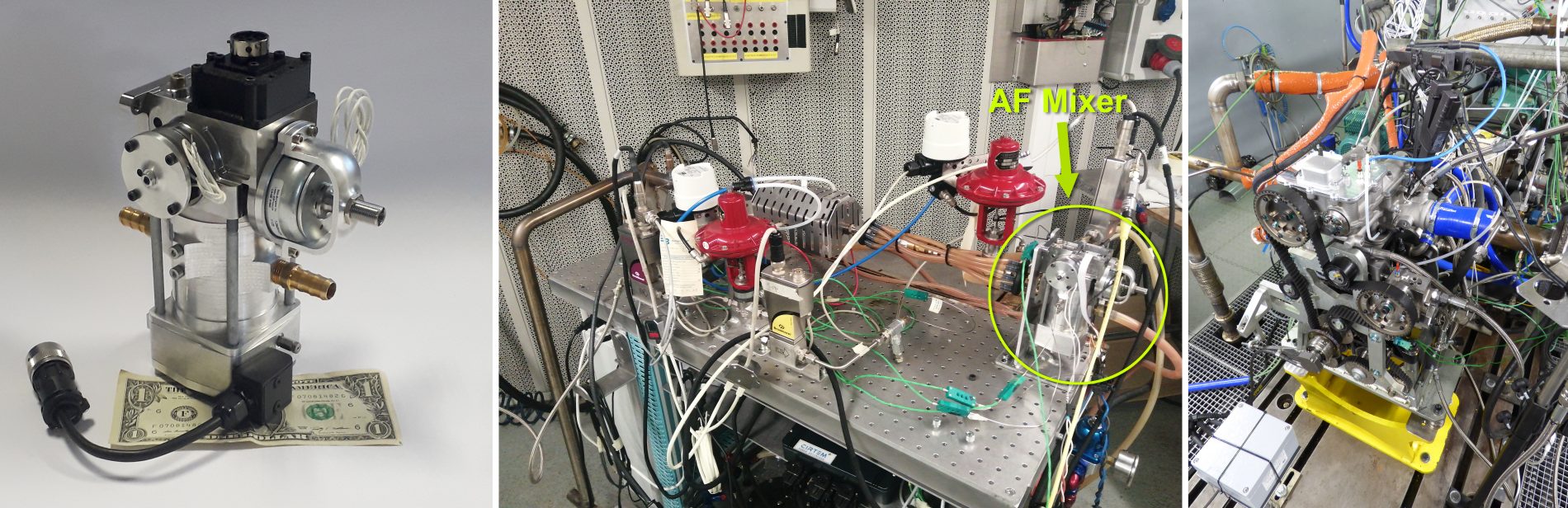
The development version shown below, on the left, made it possible to validate the mixer’s operation on a dedicated test bench (center) as well as on the engine test bench (right):
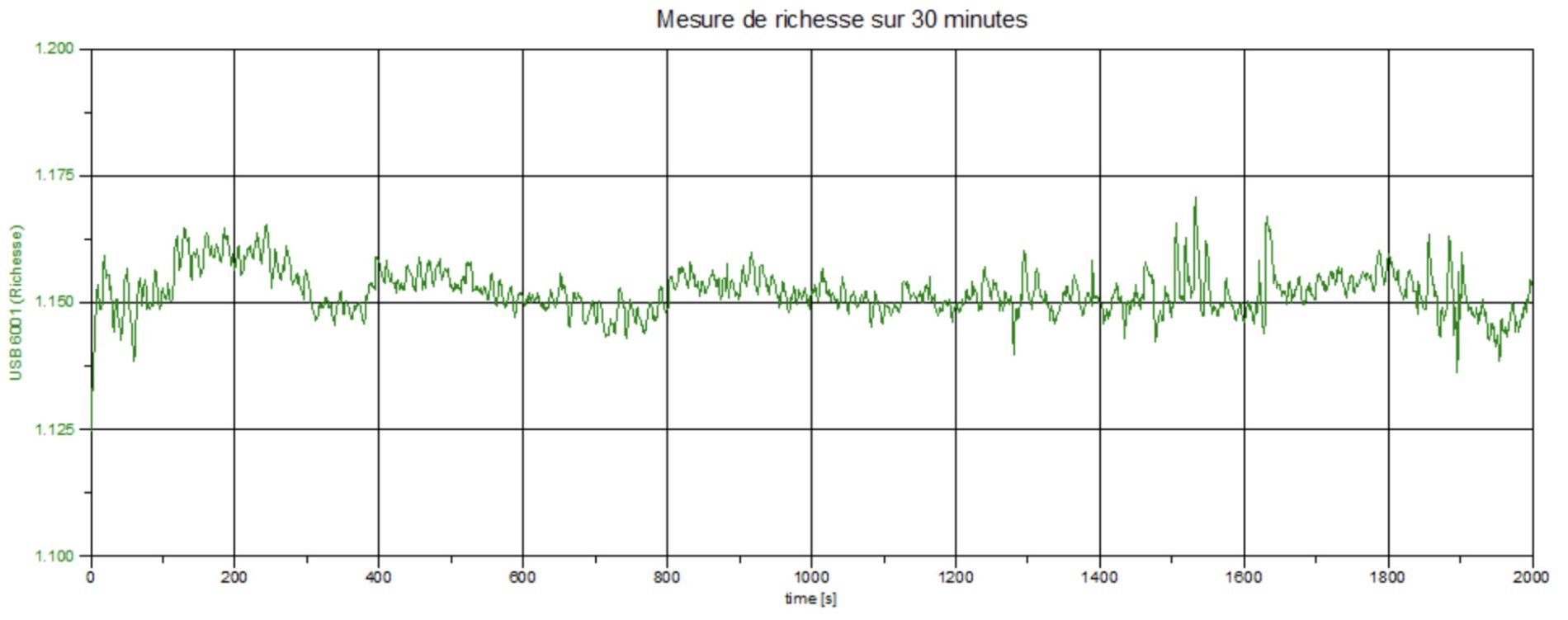
The Valvijet mixer’s mixture-richness accuracy is ±2% across the entire flow range, from idle to full power:
Already compact in its development version, the “industrial” version of the mixer is even more compact, making it easy to integrate into an engine bay, even in small vehicles:
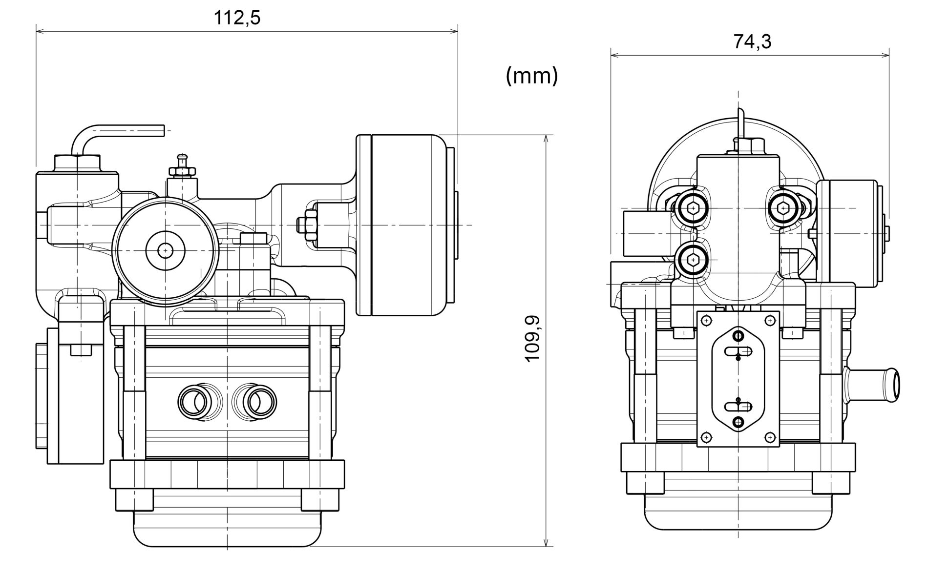
The production cost of the mixer - around €75 - has been the subject of a detailed study, involving specialists and industrial partners for each step of the manufacturing process, following a ‘design-to-cost’ approach:
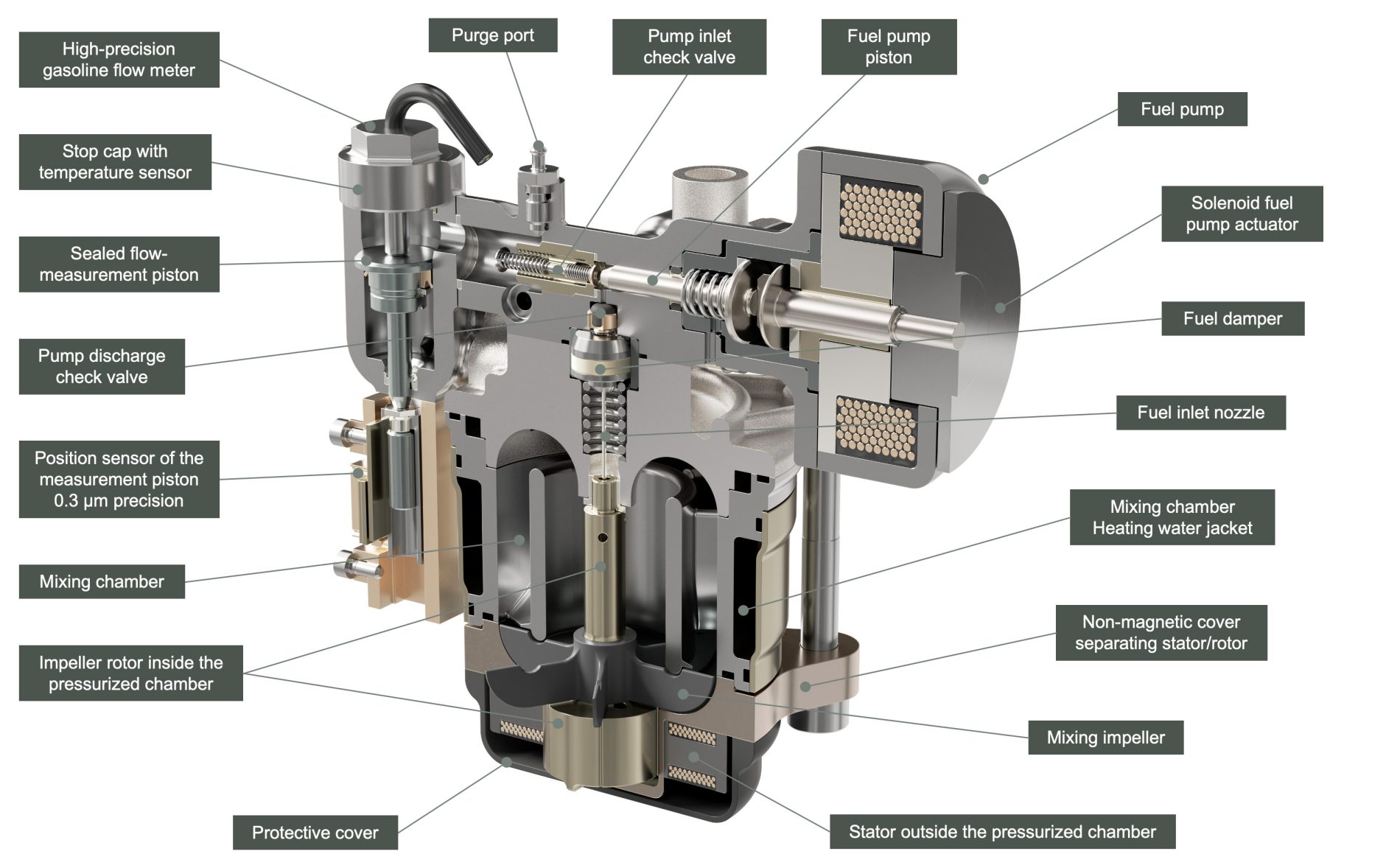
The Valvijet mixer is controlled by dedicated electronic components and proprietary software that precisely manages the air/gasoline ratio. It ensures maximum homogeneity of the pilot charge and handles all engine operating phases: cold start, stand-by, restarts, warm-up, and cooldown.
The Valvijet mixer’s ±2% mixture-richness accuracy is insensitive to pilot-charge flow rate. The initial combustion conditions in the pre-chamber are guaranteed under all circumstances.
The mixer operates as follows, in relation to the diagram below:
The richness of the pilot charge is imposed on the mixer. It evolves slowly during engine warm-up. The optimal pilot-charge richness in “hot engine” operation is 1.2 (lambda 0.8).
For each operating point, the pilot-charge injector delivers into the pre-chamber the required amount, determined during calibration. The corresponding air flow is measured by a flowmeter upstream of the mixer or inferred through algorithms.
Based on the measured air flow, the solenoid fuel pump introduces into the mixing chamber the required amount of gasoline to achieve the target richness. Its frequency varies from one cycle to the next and can reach an average of around 50 Hz.
At each pulse, the quantity of gasoline injected is measured by a high-precision flowmeter that accounts for fuel density, calculated from its temperature. The displacement of the sealed measurement piston is read by an absolute-position sensor: the indicated position is never the sum of successive displacements, but a direct reading.
Once the amount of gasoline injected by a pump stroke is determined, the resulting richness is calculated. If the quantity introduced into the mixing chamber exceeds the target value, the next pulse is proportionally delayed. In the opposite case, it is advanced. The mixing chamber continuously homogenizes the air/fuel mixture it contains, ensuring extremely small variations in the mixture drawn by the pilot-charge injectors.
When the sealed piston reaches the end of its stroke, the return solenoid valve sends it back to its initial position. During this maneuver, which lasts up to 100 milliseconds, the system temporarily operates in open loop, relying on the characterized and stored behavior of the solenoid pump. Once the piston returns to its starting point, closed-loop operation resumes.

This component is operational on the engine test bench.
To achieve stoichiometric TJI engines diluted with EGR and compatible with three-way catalysis, it is essential to inject into the pre-chamber a perfectly controlled A/F pilot charge: precise richness, homogeneous, and 100% gaseous.
There is no alternative.
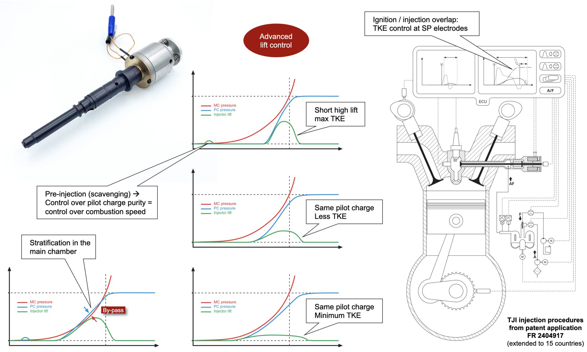
Unlike conventional gasoline injection, the angular injection window for the pilot charge is very narrow: from 30 to 40° CA at low speed, and up to 60° CA at 6000 rpm, i.e., 1.7 milliseconds. If injection starts too early, the pilot charge disperses unnecessarily into the main chamber. If it ends too late, the overlap with spark ignition becomes excessive: back-flow may occur at the injector, with a risk of fouling, and misfires may appear due to excessive turbulence between the spark-plug electrodes.
Another difference with gasoline injection: the upstream pressure of the A/F injector cannot be dynamically modulated. The pilot charge is a compressible gas, and the reaction times would be too long. In addition, the maximum permissible pressure depends on temperature, as it is limited by the re-condensation threshold of the fuel contained in the pilot charge, which strongly restricts the possibilities.
Another constraint: the introduction of the pilot charge into the pre-chamber occurs mainly under sonic flow at the A/F injector. In choked-flow conditions, only the density of the gaseous mixture matters, itself determined by its pressure and temperature. Thus, when the maximum opening duration (maximum angular window) is reached, the only way to increase the mass flow is to increase the flow area at the A/F injector, and therefore the needle lift.
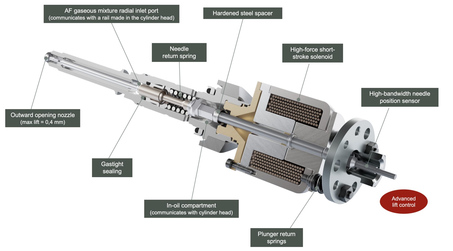
The A/F injector must therefore regulate its flow rate through needle lift (variable lift), injection duration (pulse width), or a combination of both.
Since the absolute injection duration (in milliseconds) decreases with engine speed, the faster the engine runs, the higher - but shorter - the needle lift must be to inject the same amount. Thus, to introduce the maximum pilot charge within the same angular window, needle lift must be about 15 microns at 1500 rpm and 300 microns at 7000 rpm - i.e. a lift 20 times larger for an engine speed only 4.7 times higher.
To guarantee A/F injector durability, the needle must return to its seat at a speed below 1 m/s (“soft landing”).
In certain situations, such as catalyst warm-up, cooperation between the A/F injector and the Valvijet check valve is critical. Injecting the pilot charge causes the valve to open several tens of crank degrees after top dead center, simultaneously with spark ignition. The A/F injector then feeds the combustion with a thin stream of gas. This specific sequence requires high flexibility and precise control of needle lift.
Another essential point: ensuring strictly identical needle lift for all injectors on the same engine. In this case, the unit flow rate of each A/F injector equals the flow rate of the A/F mixer divided by the number of cylinders. The pre-chamber ignition system can then be considered as a “large spark plug,” independent of the main injection system. It becomes possible, in particular, to use closed-loop control via the lambda sensor without disturbing pre-chamber operation, and to control the engine with the same finesse and freedom as with a conventional spark-ignition system.
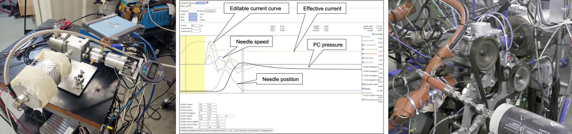
This is why the Valvijet A/F injector incorporates a wide-bandwidth needle-position sensor.
This sensor makes it possible to correlate the coil current curve driving the solenoid with the actual needle lift. The current is therefore adjusted according to each injector’s individual response to meet the lift target precisely. Through learning, this approach becomes predictive and guarantees correct dynamic needle lift while continuously accounting for its mechanical and magnetic characteristics. A supervisor controls all A/F injectors.
Needle lift is also used for consistency checks between the flow measured at the A/F mixer and the flow expected from the sum of the A/F injector lifts. These data also feed the OBD (On-Board Diagnostic) system.
Diagnostic correlations also exist between the air-compression system, the A/F mixer, and the A/F injectors, as well as with instantaneous torque measurements derived from the crankshaft angle encoder. These correlations make it possible, among other things, to infer the operating conditions of the Valvijet check valve.
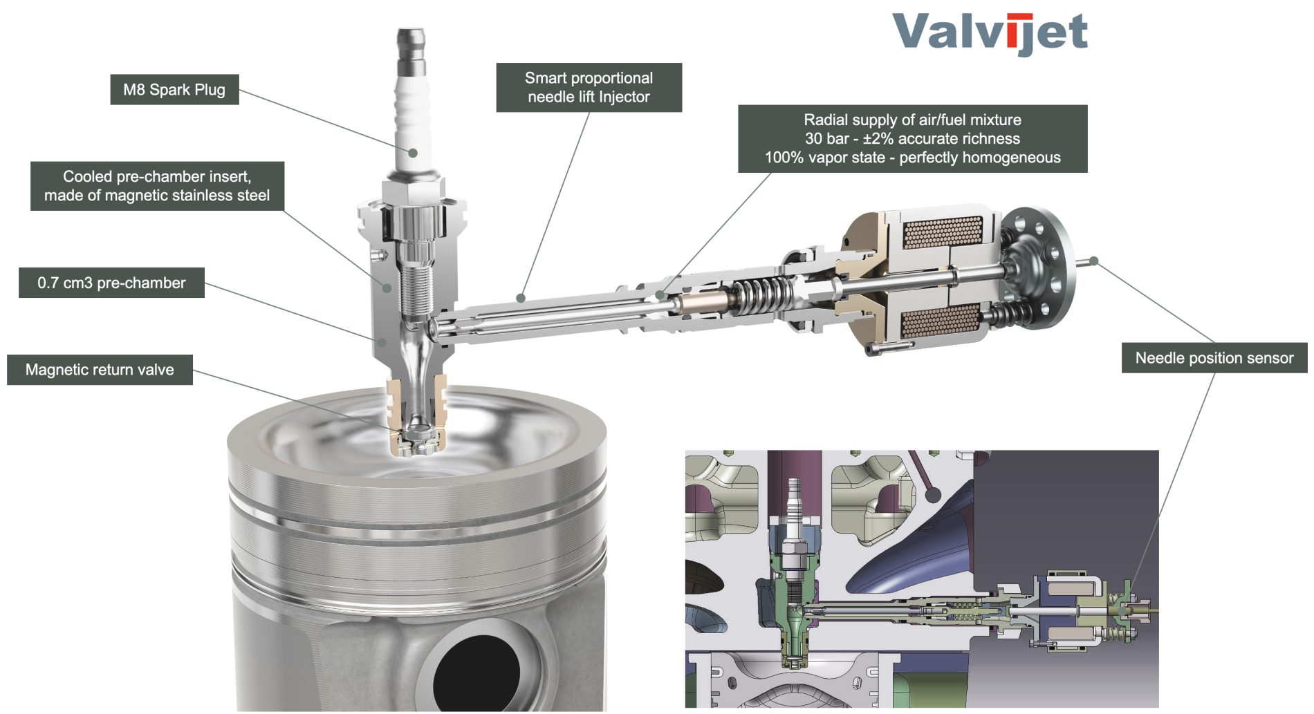
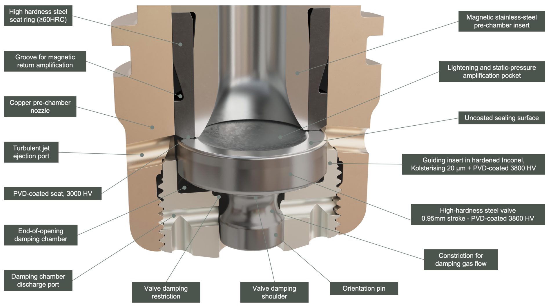
The Valvijet A/F injector features a specific architecture: a radial gas inlet and internal sealing that isolates the pressurized zone from the crankcase-pressure zone. The radial inlet is fed by a distribution manifold machined into the cylinder head, through which the A/F pilot-charge mixture flows. This configuration maintains the A/F mixture at engine temperature, preventing any partial re-condensation of the fuel.
The configuration of the Valvijet A/F injector is as follows:

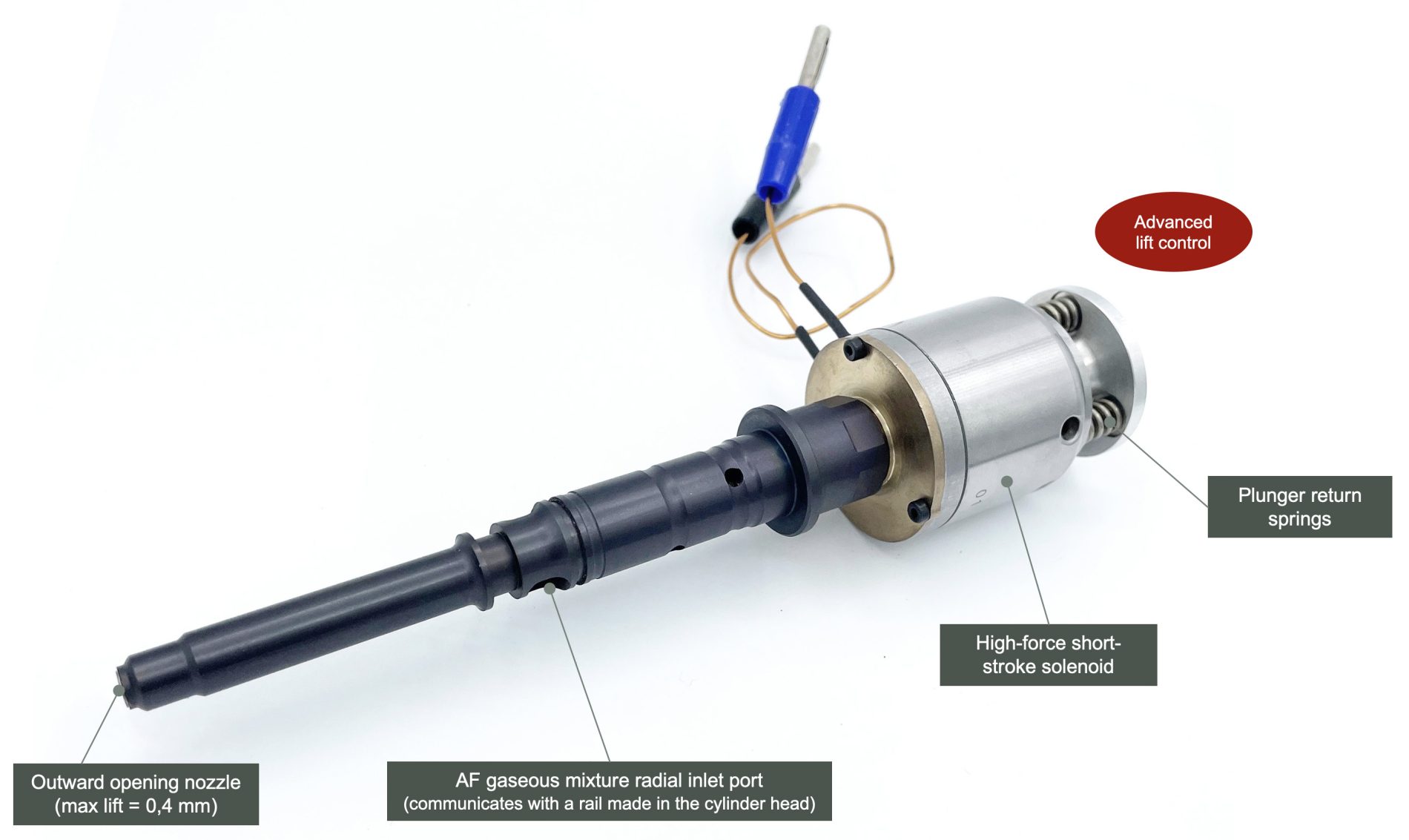
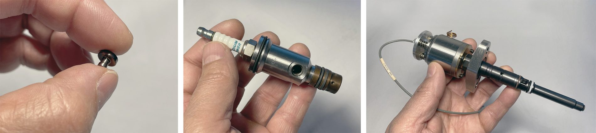
The Valvijet A/F injector has undergone several years of development and many design variants:
The diagrams below illustrate the wide variety of injection strategies enabled by the Valvijet A/F injector:
This component is operational on the engine test bench.
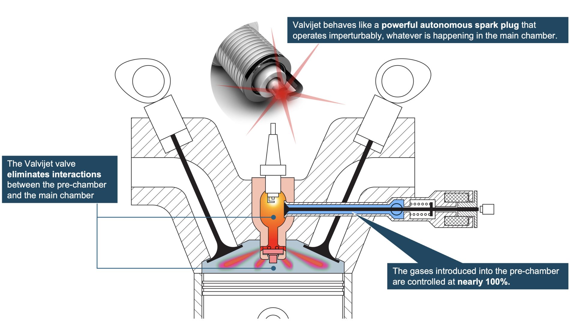
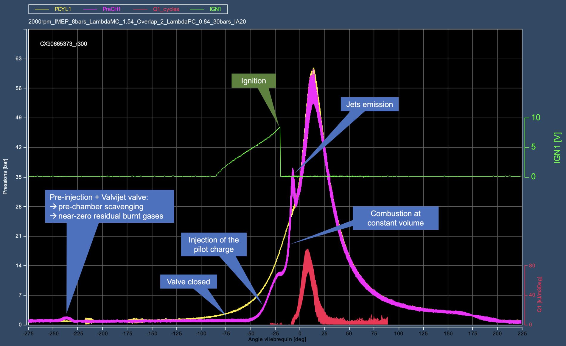
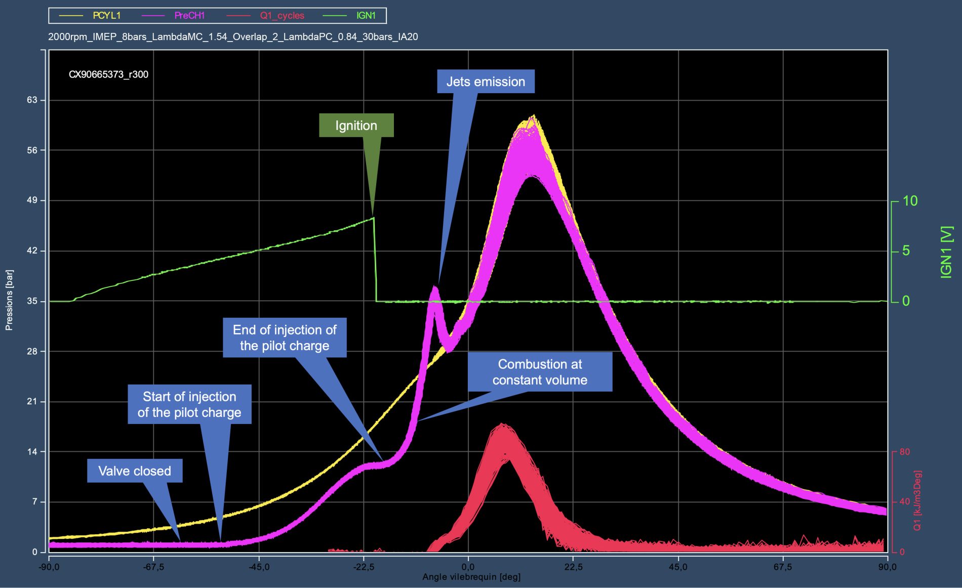
The check valve fulfills many functions, the first of which is to guarantee optimal initial conditions in the pre-chamber at the beginning of each cycle. These conditions are adjusted for every engine operating point, with no “memory” effect: each cycle is independent and never influenced by the previous one.
Residual burnt gases (RBG) and low-load operation:
Residual burnt gases (RBG) are the main weakness of pre-chamber ignition systems - the Valvijet check valve eliminates them.
In a passive pre-chamber, without a valve, the RBG rate increases as engine load decreases. Beyond a certain threshold, ignition becomes unstable or even impossible. Yet low loads dominate both WLTP cycles and real-world conditions (RDE): the engine operates more than 80% of the time below 3 to 4 bar BMEP. The effective average fuel consumption therefore depends mainly on these operating zones.
By eliminating RBG, efficiency becomes high again at low loads, yielding decisive benefits:
High efficiency at low loads = avoiding “hard downsizing”. Hard downsizing is costly to manufacture and risky in terms of reliability due to the high thermal and mechanical stresses it imposes. The dynamic performance of such engines relies heavily on turbocharging. Strategies used to reduce turbo lag in transients (turbo spooling) consume a lot of fuel: over-injection, post-injection, spark retard, throttling. Fuel consumption then becomes very sensitive to driving style, especially in urban use: real-world fuel consumption often exceeds official values by 20% to 40%.
Thanks to the high efficiency achieved at low loads, and except for specific high-performance applications, a Valvijet engine will not exceed 16–17 bar BMEP (“de-rating,” “right-sizing”), compared to 21–22 bar for modern turbocharged GDI engines.
High efficiency at low loads = reduced need for hybridization. If an engine is naturally efficient, it makes little sense to avoid low-load operation through an expensive cascade of mechanical and electrical conversions. This is why Diesel engines are rarely hybridized. However, regenerative braking remains a strong advantage of hybrid systems, especially in urban driving. The two approaches can therefore be combined for maximum efficiency, creating new cost/efficiency trade-offs that optimize vehicle pricing in the “core market” segment.
Hence the crucial importance of eliminating RBG in pre-chambers at the beginning of every cycle.
With the Valvijet pilot-charge supply system (A/F mixer, A/F injectors), even without a check valve, a scavenging pre-injection already significantly reduces RBG compared to a passive pre-chamber. However, the Valvijet check valve goes much further: after the scavenging pre-injection, it prevents any re-entry into the pre-chamber of gases coming from the main charge, which is intended to be diluted by EGR. The RBG level in the pre-chamber therefore tends toward zero - a true game changer.
RBG strongly reduce flame speed. As an order of magnitude, diluting an air–fuel mixture with only 15% RBG (or EGR) reduces laminar flame speed by 50% and turbulent flame speed by 20%. Yet in a conventional passive pre-chamber, 40–50% RBG are typically observed at 2 bar IMEP, and still 30-40% at 4 bar IMEP. The residence time of hot gases in the pre-chamber increases, causing greater cooling against the walls.
Furthermore, RBG thicken the flame quenching layer near the walls. As an order of magnitude, this layer becomes twice as thick with 20% RBG compared to zero RBG. Given the high surface-to-volume ratio of a pre-chamber, this thickening produces a large amount of unburnt hydrocarbons, reducing the energy released by combustion and lowering turbulent jet temperature.
RBG also increase the specific heat capacity of the pilot charge relative to its energy content: there is less fuel per unit mass. This again contributes to reducing jet temperature.
But colder turbulent jets are less effective at igniting the main charge. They approach the ignition temperature limit and may even extinguish due to flame quenching when mixing with the cold main charge before triggering its combustion.
Another major effect of RBG is instability. They deteriorate ignition, flame propagation, and the thermochemical stability of combustion. The flame becomes fragile. In the pre-chamber, slow and fast combustions alternate from one cycle to another. Turbulent jets emerge from the pre-chamber with several crank-angle degrees of variation between cycles. These variations have a disastrous effect on combustion stability in the main chamber, as the latter amplifies instabilities originating from the pre-chamber.
Engine operating robustness under high EGR dilution:
With the Valvijet check valve, the pilot charge consists exclusively of the fuel–air mixture injected into the pre-chamber by the A/F injector. The main charge no longer influences its composition, its quality, or its quantity. The EGR dilution limits of the main charge are therefore drastically extended, and the engine remains stable.
With Valvijet, even at low loads, the stability limit (COV ≤ 3%) is only reached at around 45% external EGR. Yet an engine must be able to operate with at least 35-40% EGR to absorb unavoidable EGR spikes during transients without instability or misfiring. In theory, the thermodynamic efficiency optimum lies around 30% external EGR. But this optimum is only practically achievable if the engine can tolerate, without degradation, 35-40% EGR during load and speed variations. Otherwise, EGR must be limited to 15-20%, far below the optimal zone, to stay safe and avoid transient dropouts (instabilities, misfiring).
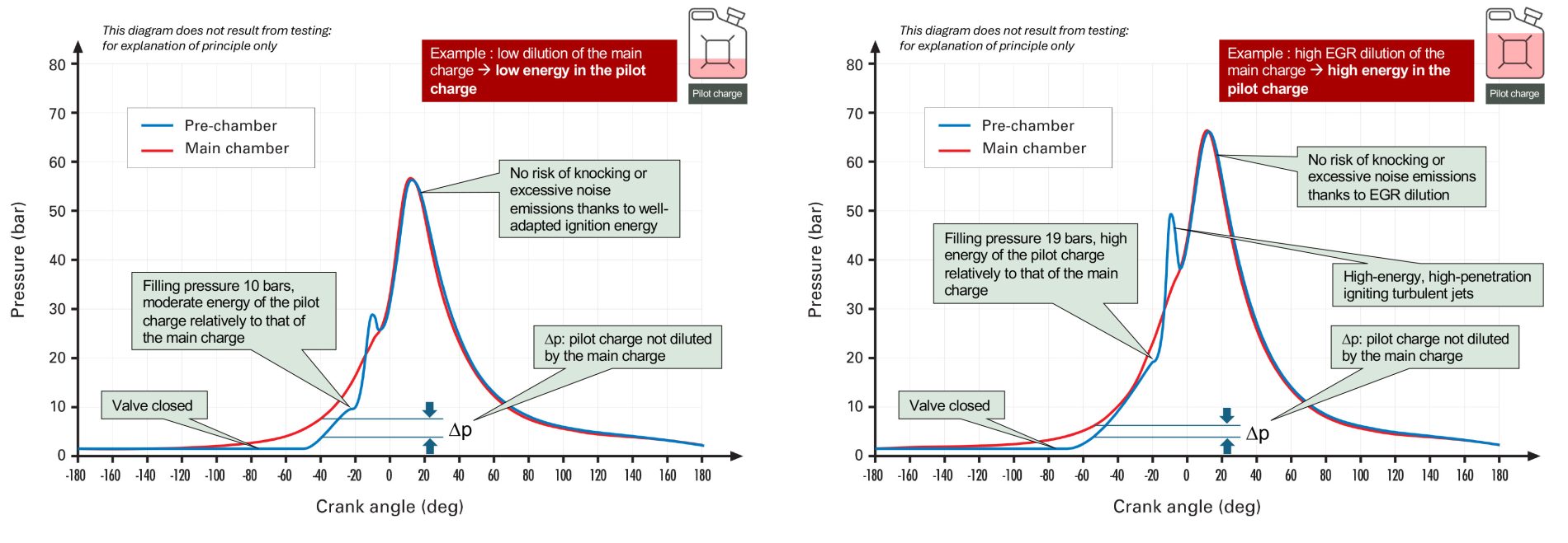
The more EGR the main charge contains, the more powerful and reactive the pilot charge must be to ensure ignition. However, nothing prevents the pilot charge from being temporarily more energetic than necessary to absorb a possible excess of EGR - even if that excess does not materialize. This is the strategy to guarantee engine stability during EGR transients while operating at the EGR rate that maximizes efficiency, around 30%.
At low loads, it is ideal to favor internal EGR (i-EGR), which is hotter - supporting more efficient combustion - and more voluminous, contributing to reduced pumping losses. The ratio of i-EGR to external EGR (e-EGR) within the main charge is managed through appropriate exhaust VVT phasing. This lever effectively optimizes efficiency at low loads, with no interaction whatsoever with the pre-chamber, which is fully isolated by the Valvijet check valve.
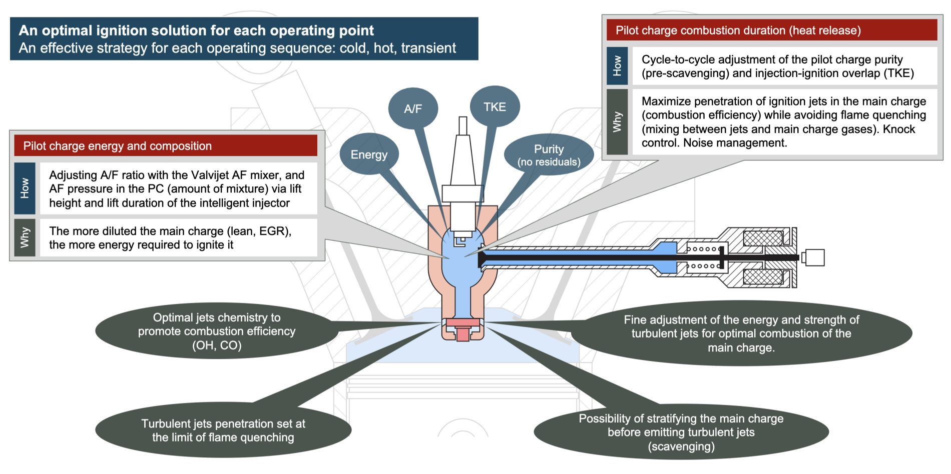
Adjustment of turbulent-jet energy and intensity:
Under high EGR dilution, mastering the energy and strength of the turbulent jets is critical.
If the pilot charge burns too quickly, the main charge may fail to ignite entirely: the turbulent jets then mix excessively with the cold gases of the main charge, preventing combustion from starting (thermal quenching). Conversely, a pilot charge that is insufficiently energetic can lead to the same outcome.
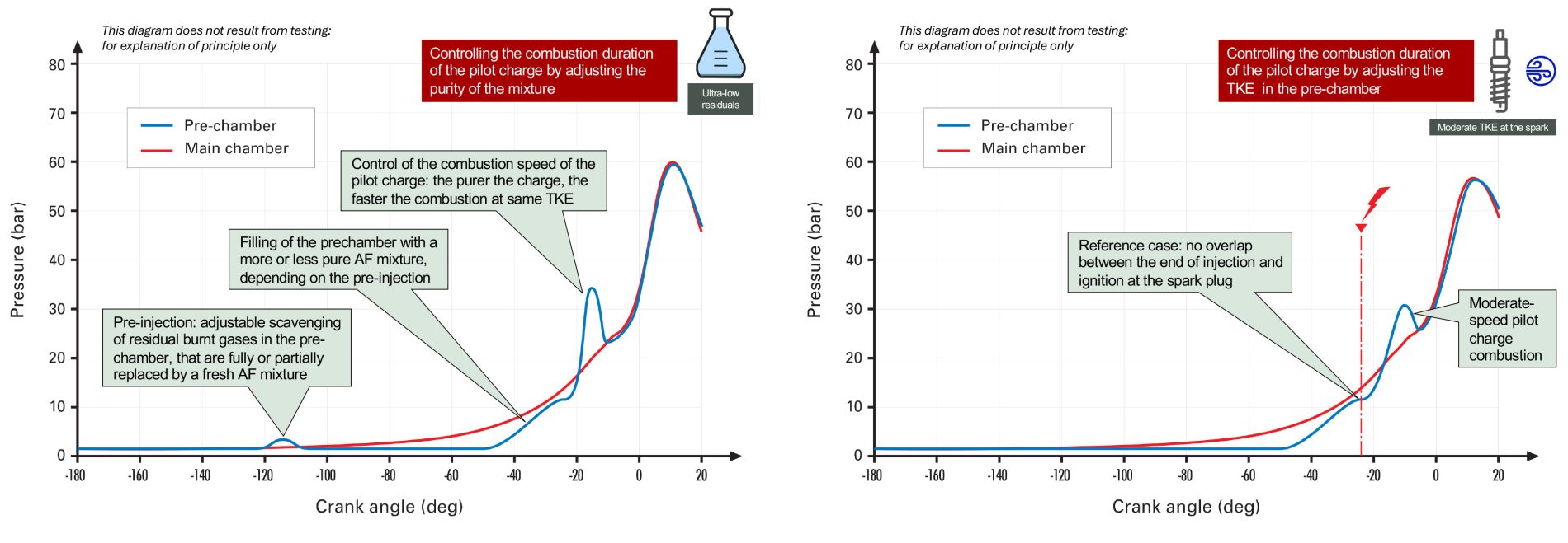
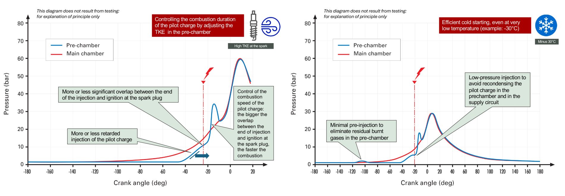
The Valvijet check valve allows both the quantity of energy introduced into the pre-chamber and the combustion speed to be controlled by modulating turbulence. Practically, this consists of adjusting the overlap between the end of A/F injection into the pre-chamber (closed by the valve) and the spark ignition of the pilot charge. This precise, perfectly repeatable adjustment tunes the penetration of the turbulent jets into the main chamber and identifies the optimal compromise between jet energy and jet strength - that is, the compromise that maximizes overall thermodynamic efficiency.
Pre-chamber filling:
A pressure of around 30 bar upstream of the A/F injectors represents a good compromise. Beyond this value, the risks of partial re-condensation of the pilot-charge fuel increase, while the energy required for air compression and the technological constraints on the compressor rise proportionally.
Without the Valvijet check valve, with 30 bar upstream of the A/F injectors and at high boosted loads, the flow at the injector becomes subsonic. The available angular window at high engine speeds is then insufficient to introduce the entire pilot charge within the allotted time, even with maximum needle lift. Beyond a certain load, backflow may even occur at the A/F injectors.
With the Valvijet check valve, since the pre-chamber is closed, injection remains possible under all conditions with an upstream pressure of only 30 bar.
Spark plug lifetime:
The Valvijet check valve ensures a pilot charge free of residual burnt gases, with controlled pressure at the moment of ignition. These two parameters are critical for spark-plug lifetime, especially given the small diameter imposed by the limited space in the pre-chamber.
The Valvijet single-cylinder prototypes use an 8 mm Denso IY24 spark plug protruding into a 700 mm³ pre-chamber. Ignition occurs at a relatively low voltage and with an energy always below 50 millijoules, which ensures long spark-plug life despite its compact size.
Calibration and torque control:
With the Valvijet check valve, the pre-chamber is isolated from the main combustion chamber. This makes it possible to greatly widen the ignition timing window while maintaining excellent combustion stability (COV).
This feature provides substantial freedom to control torque during transients by modulating efficiency through spark retard - just as with a conventional spark plug - or by temporarily disabling a cylinder. This point is crucial: this mode of torque control, which is difficult or even problematic with conventional pre-chambers, is essential for calibrating an automotive engine without relying on electric assistance.
Cold start:
At -35 °C, a stoichiometric air–fuel mixture (lambda = 1) does not re-condense - even partially - as long as the pressure remains below 4 to 5 bar.
In a pre-chamber without a check valve, a significant portion of the pilot charge comes from the main chamber. During the transfer of these gases from the main chamber to the pre-chamber, part of the fuel they contain re-condenses around the turbulent-jet orifices. This leans the A/F mixture in the pre-chamber and makes it harder to ignite, in addition to the negative effect of residual burnt gases (RBG) on combustion quality.
With the Valvijet check valve, 100% of the mixture present in the pre-chamber comes from the pilot-charge A/F injector. There are no RBG, and the pressure in the pre-chamber is deliberately limited to 5 bar at the moment of injection and up to pilot-charge ignition by the spark plug, regardless of the pressure in the main chamber.
Furthermore, the absence of RBG dilution raises the temperature of the turbulent jets, improving their ability to ignite the main charge. Since the main charge is relatively cold, the valve makes it possible to adjust the pilot-charge quantity and turbulence level via the A/F injector. This tuning prevents excessive mixing between the turbulent jets and the main charge and eliminates any risk of flame quenching.
The Valvijet fueling system and Valvijet check valve thus provide all the necessary levers to ensure strong starting performance at any temperature.
Catalyst warm-up:
Since the Valvijet check valve forms, together with the pre-chamber, a closed volume at a lower pressure than the main chamber, it becomes possible to delay ignition without overcompressing the gases contained in the pre-chamber after Top Dead Center (TDC) and then expand them before combustion.
The most effective strategy for heating the catalyst is to operate with the throttle wide open to maximize the flow of hot gases: the warm-up time depends on the ratio of heat capacities between the hot gases and the catalyst.
If the throttle is fully open and the pre-chamber is not isolated by the Valvijet check valve, then on a high-compression-ratio engine (>13:1), the gases in the pre-chamber are compressed to around 28 bar. They heat up due to compression but cool again upon contact with the pre-chamber walls. They are then re-expanded until the ignition point, which must occur late - at least 30° after TDC. This expansion cools the gases, creating a “heat pump” effect. The temperature of the pilot charge drops rapidly, causing part of the vaporized fuel to re-condense. Combustion then becomes impossible.
Another impossibility without a check valve: injecting the gaseous air–fuel pilot charge when the throttle is wide open. During a cold start, for example at 15 °C, the maximum allowable pressure to avoid re-condensation is about 15 bar. Yet late injection takes place when pressure in the main chamber is around 20 bar - making the operation incompatible.
To solve this problem, the Valvijet check valve limits the pre-chamber pressure at the moment of injection to intake pressure - around 1 bar - compared to 20 bar without a valve. This difference makes injection possible, as shown later with test-bench data.
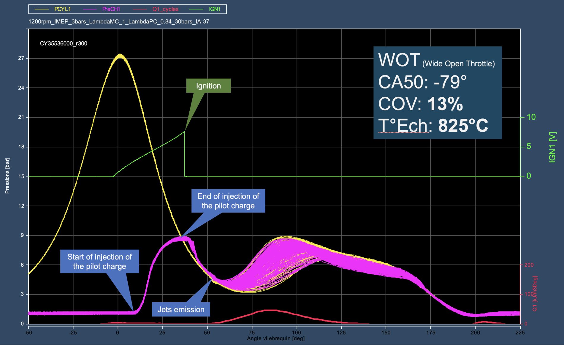
With the current Valvijet check valve, which continues to evolve (more than 70 configurations tested since 2019), it is already possible to ignite at 37° after TDC, throttle wide open - that is, with maximal gas flow - while maintaining acceptable COV and exhaust temperatures above 850 °C.
Below is the configuration of the late-2025 Valvijet check valve:
The Valvijet check valve has been the subject of particularly intensive Research and Development since 2018. This work has made it possible to identify all the key factors governing its operation and to meet a demanding set of specifications:
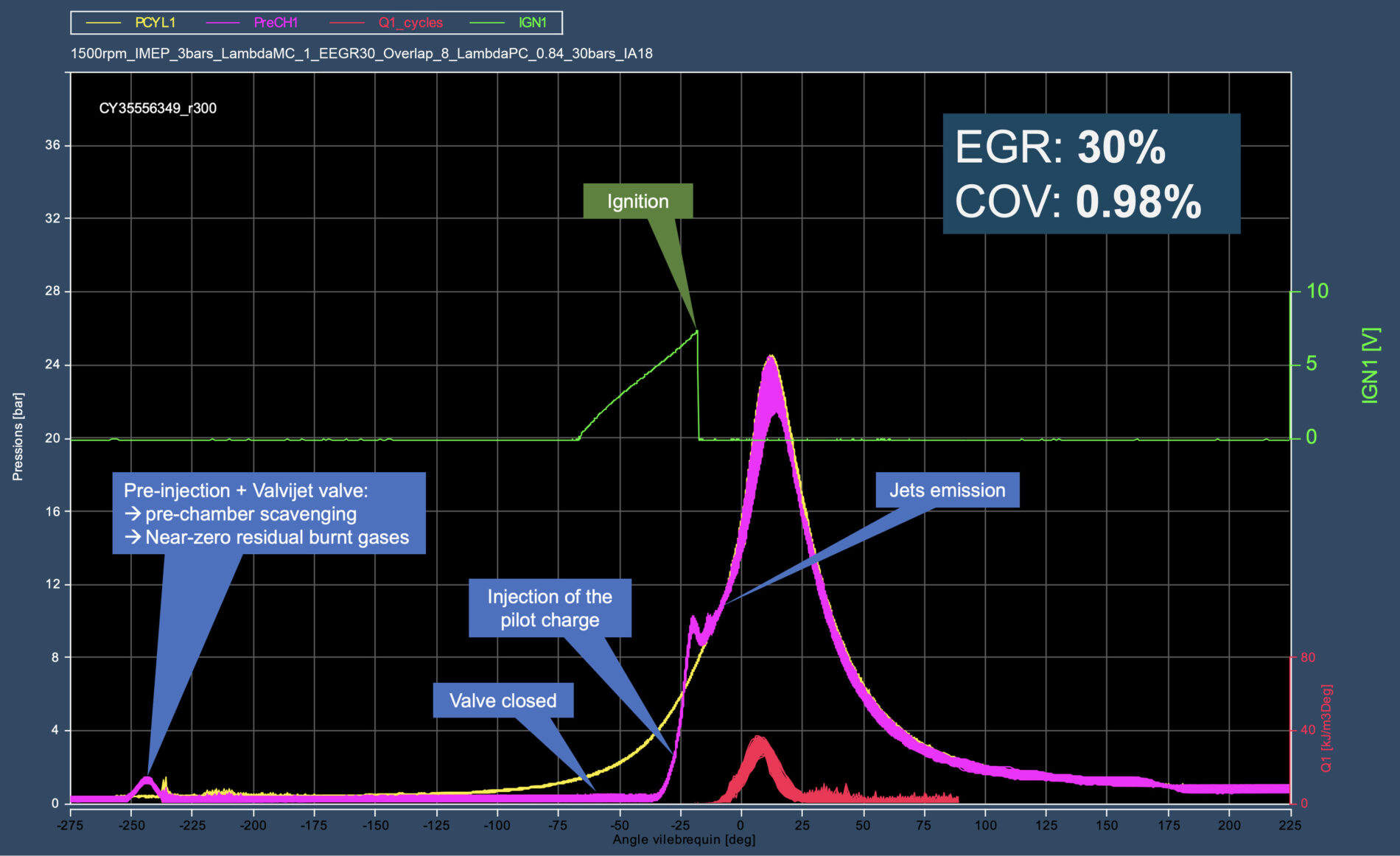
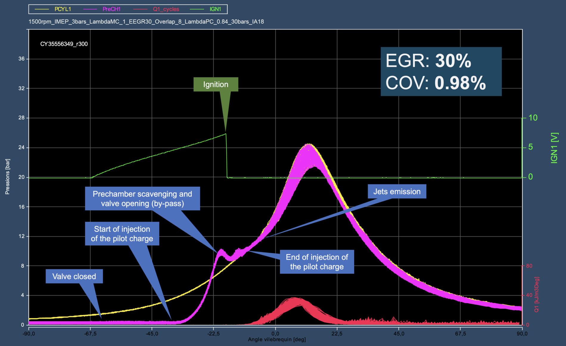
Below are examples of diagrams of 300 stacked cycles, measured at medium and low loads on the test bench at various operating points. These curves show the effect of the combined valve + pre-injection strategy on combustion efficiency and stability.
Below is the typical operation of the valve under standard conditions, shown here in lean operation:
The coefficient of variation (COV) of 0.4% observed above results from the repeatability and ignition stability provided by the Valvijet system, which guarantees controlled initial conditions in the prechamber. This stability contributes to low NVH at low engine speed. In addition to precise combustion phasing that consistently maintains an optimal CA50, this stability facilitates engine “downspeeding”, meaning operating at lower rpm for higher load and improved real-world efficiency.
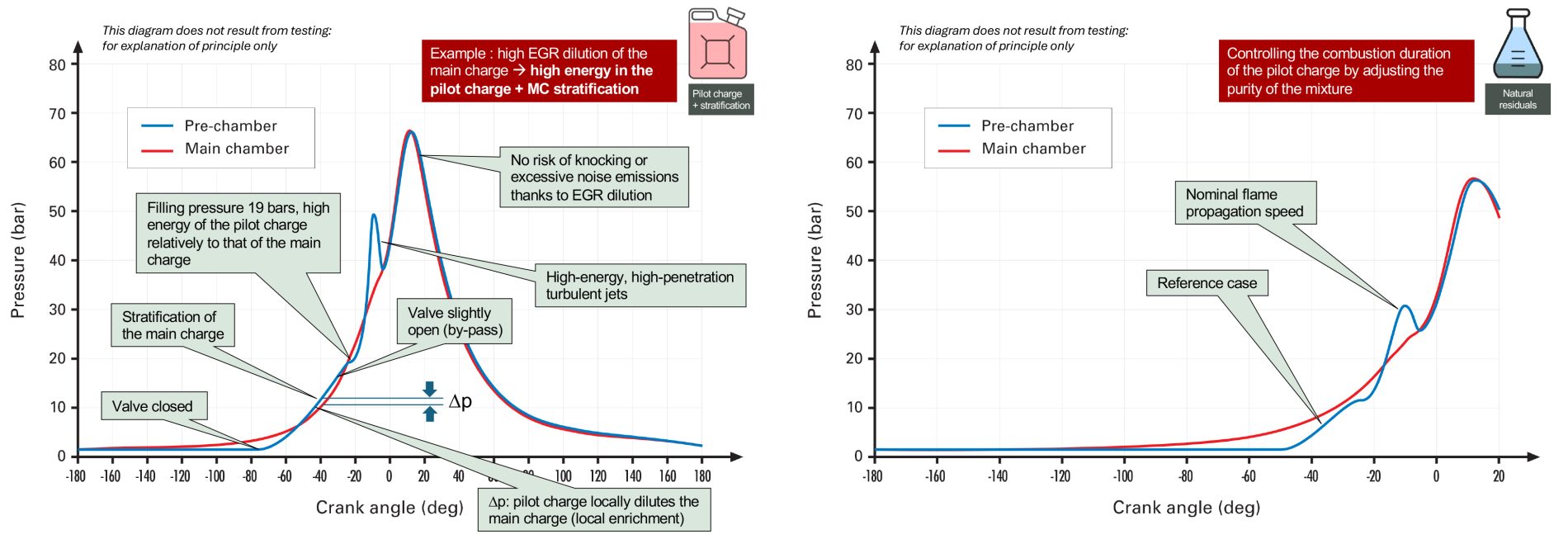
Another way to use the Valvijet system is to stratify the region surrounding the prechamber tip with fresh gases, by scavenging the prechamber at the end of its filling with pilot charge.
This approach is particularly effective at high EGR rates (>30%), including at low loads where EGR sensitivity is greatest. Additional strategies are under study to further reduce pilot charge consumption, notably through a more responsive valve during opening and increased internal EGR, which is not achievable with the Diesel single-cylinder engines currently used for development.
The next Valvijet prototypes, this time developed on gasoline engine platforms, will open new avenues for optimization, even though the primary objective of the Valvijet project is not to perfect the engine / ignition-system interactions.
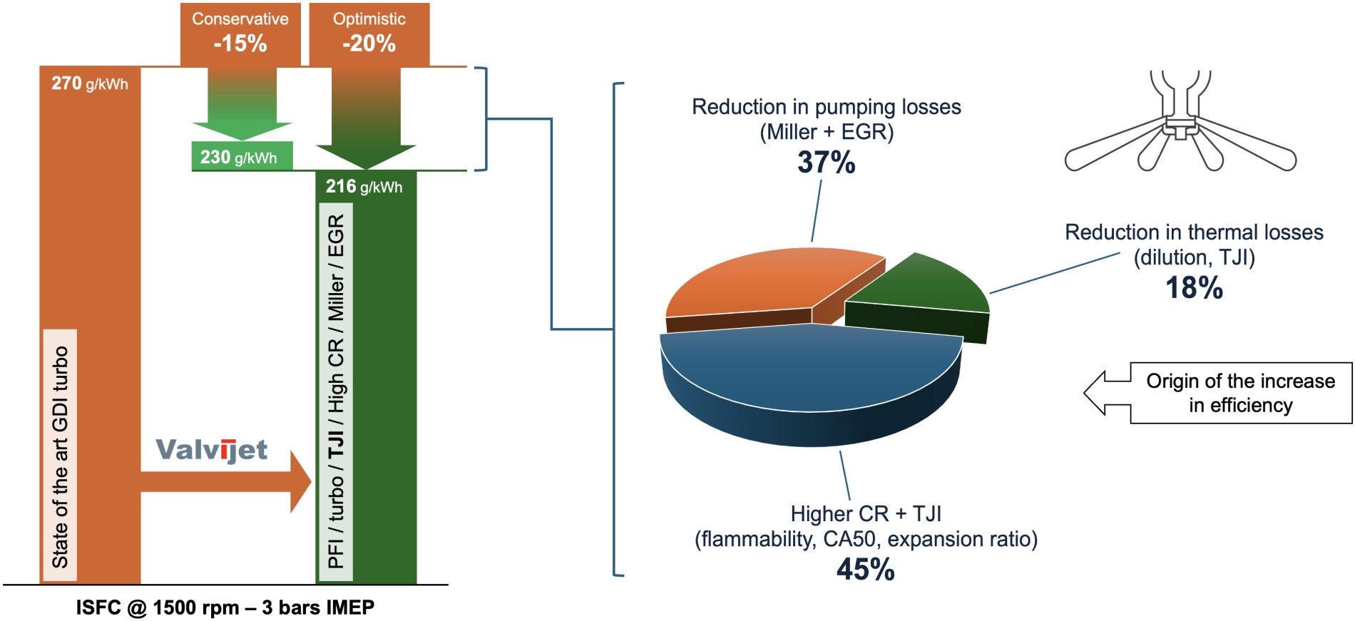
Minimizing pilot charge consumption is one of Valvijet’s intrinsic strengths. In this respect, it is noticeable that for a given EGR rate, the required pilot-charge quantity is not proportional to engine load. With 30% EGR, at 2000 rpm – 8 bars, only 2.5% pilot charge is needed, whereas 7% is required at 1500 rpm – 3 bars. In relative terms, the energy cost of compressing the pilot charge is therefore higher at 1500 rpm – 3 bars. However, the relative benefit compared with state-of-the-art turbocharged GDI engines is also greater in this zone, due to the drastic reduction in pumping losses.
At 1500 rpm – 3 bars, the origin of the efficiency gains can be summarized as follows:
The key objective is to find the best compromise between the energy cost of the pilot charge and the thermodynamic benefits provided by TJI - something Valvijet enables with maximum flexibility.
Regardless of engine speed or load, the optimal EGR rate also depends on the engine’s combustion system, independently of Valvijet. EGR tends to reduce combustion efficiency: a poorly designed combustion system may drop to 93-94% burned mass, whereas an efficient system reaches 97-98%. The end gas, mainly located between the turbulent jets, can extend the CA50-90. Solving this phenomenon requires optimizing the geometry of the combustion system: chamber, ports, and valve lift profiles. This must be complemented by suitable prechamber features: number, diameter, and orientation of the jet orifices.
Below is an engine operating point at 1500 rpm with 30% EGR, obtained with a combustion system that is still largely improvable, using a prechamber scavenging strategy during the final phase of pilot-charge filling:
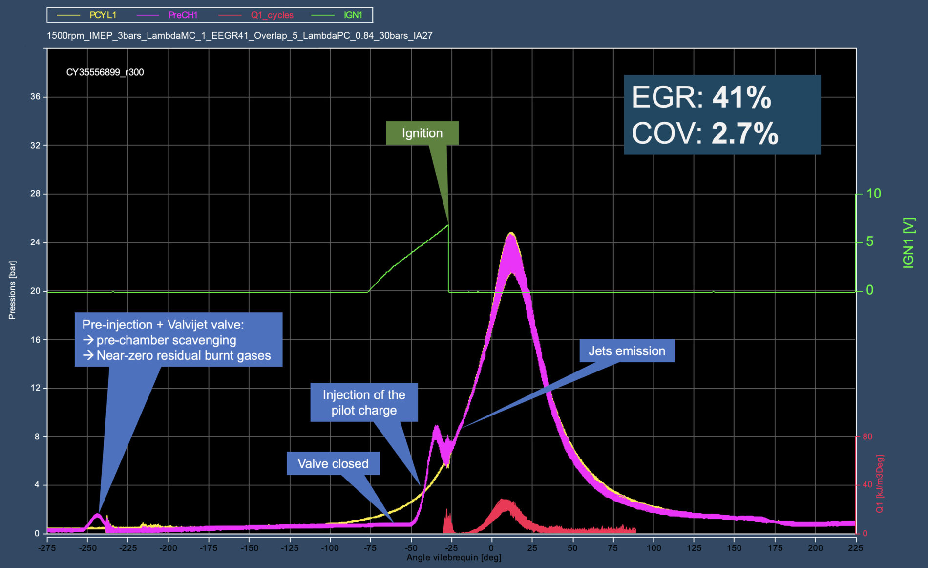
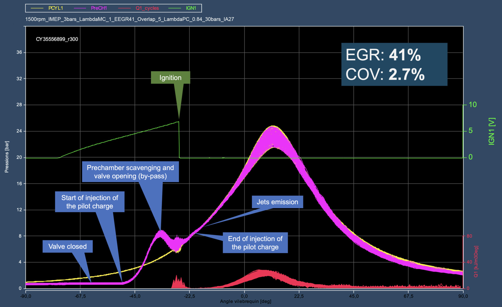
At 3 bar IMEP, the optimal EGR rate for efficiency lies between 25 and 28%. However, during transients, the engine must be able to accept an external EGR rate exceeding 40% while still maintaining a COV below 3%. This stability is achieved at the cost of a temporarily higher pilot charge. In the example below, it reaches 9% of the total energy, with an EGR rate of 41%:
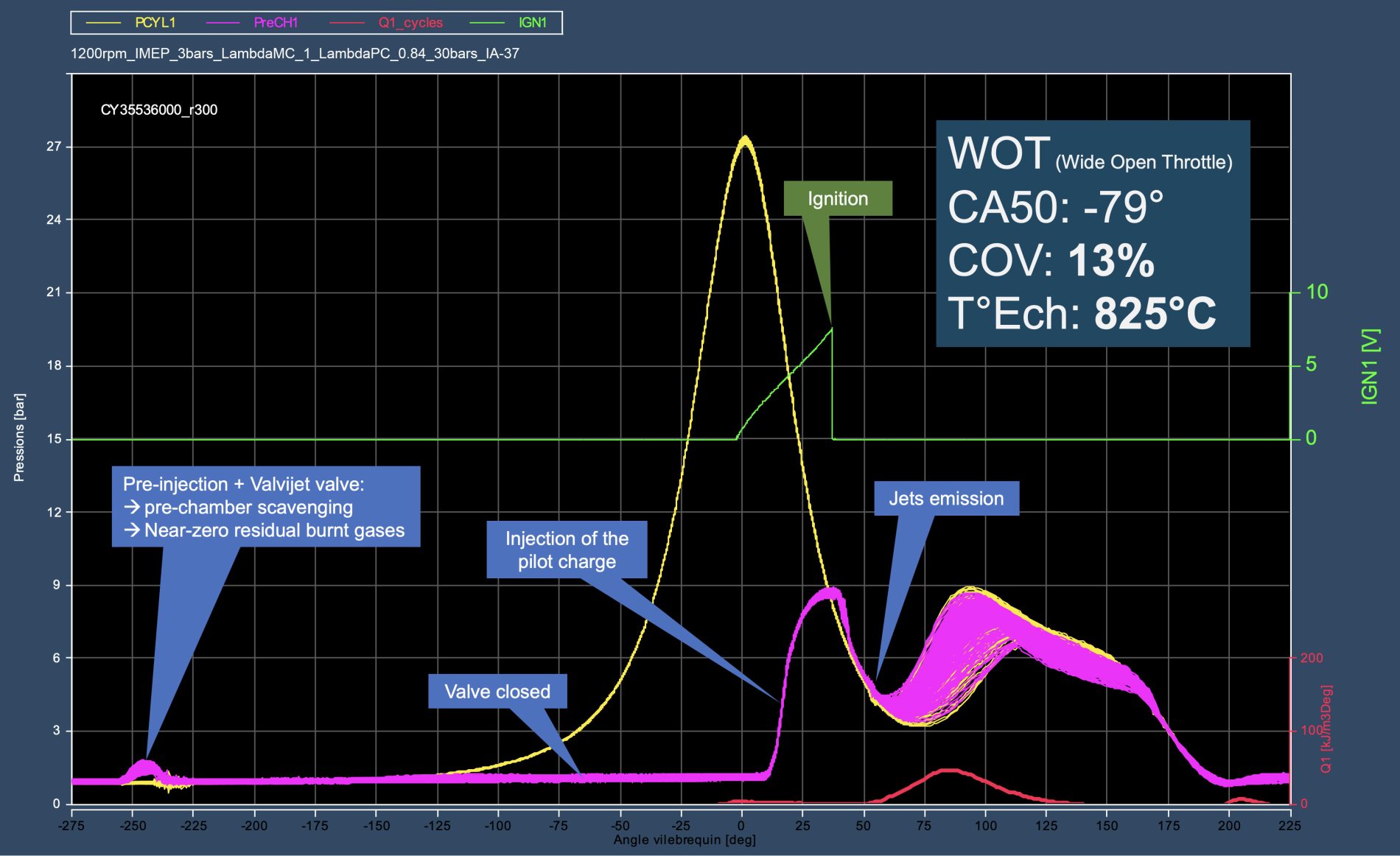
With Valvijet, catalyst warm-up becomes possible in TJl. So far, testing has revealed a load limit of 3 bar IMEP, below which the engine becomes unstable. This result is obtained with the throttle fully open to maximize the flow of hot gases exiting the exhaust valve at 825 °C. The next valve versions should allow us to go below 2 bar IMEP.
Catalyst warm-up requires firing as late as possible-something Valvijet enables under excellent conditions (ignition at 37° ATDC)-and then burning as slowly as possible with the highest possible combustion efficiency. The goal is to emit as few pollutants as possible during this phase: on WLTP, roughly 70 % of HC and 50 % of CO are emitted before light-off.
An effective strategy would be to couple the Valvijet TJI engine with mild hybridization based, for example, on a 12 V or 48 V BSG (Belt-integrated Starter Generator). This type of system is rapidly becoming widespread: in Europe, nearly 25% of new cars are already equipped with it, including entry-level models such as the new Fiat 500. During catalyst warm-up, a BSG can draw at least 2.5 kW from the crankshaft at 1 200 rpm. This prevents dropping below 3 bar IMEP on a 1.8 L engine whose cold FMEP is around 1.5 bar.
At least two options are available to make useful use of these 2.5 kW, regardless of the battery's SOC:
Below are examples of how the AF valve/injector coupling is used, illustrating the Valvijet system’s ability to adapt to different engine operating conditions:

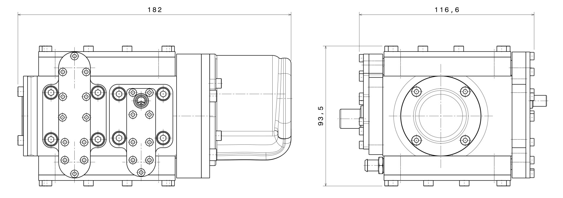
The Valvijet compressor is driven by an integrated electric motor via an internal ring and pinion. It is connected only through power and control cables, as well as fluid lines (air and water). Designed for easy integration into any vehicle, it is a generic, compact, and highly standardized component. Like the Valvijet mixer, a single compressor model can equip a wide range of vehicles - for example, those with power outputs between 50 and 150 kW.
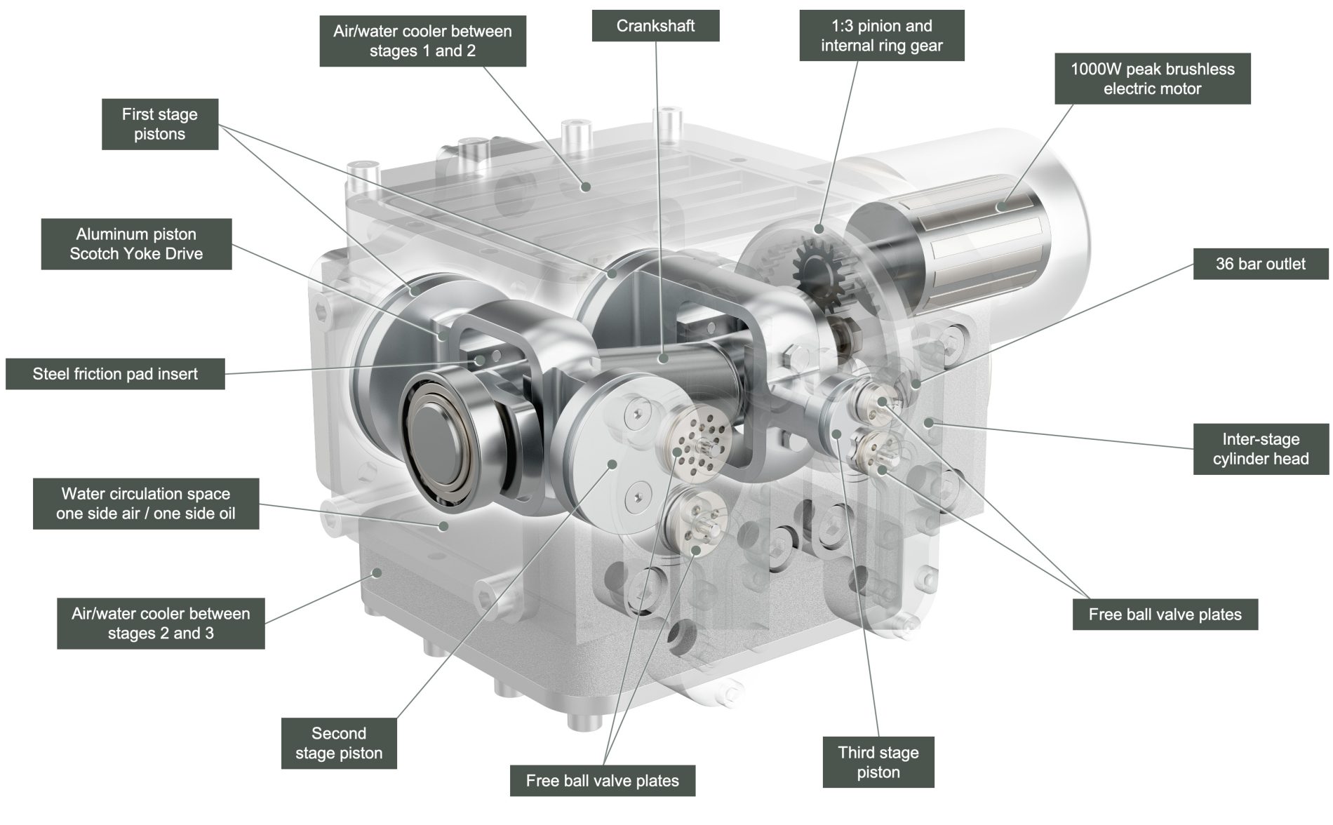
The characteristics of the Valvijet compressor are as follows:

Objective of the Valvijet compressor: high energy efficiency, zero maintenance, an ultra-compact and lightweight assembly, low vibro-acoustic emissions, and a manufacturing cost below €100.
The Valvijet compressor’s scotch-yoke mechanism includes two pairs of opposed pistons. This configuration distributes the first compression stage - the largest in volume - across two cylinders. This contributes to the compactness of the unit and helps limit mechanical loads: pressure and inertia forces largely cancel each other out, reducing stresses on the crankpins.
In the Valvijet system, compression efficiency is particularly important because it directly affects overall engine efficiency. On average, the Valvijet compressor costs less than 1% relative efficiency: for a given operating point, if the engine’s efficiency is 45% without the compressor, with the compressor it will be 44.55% (45 – 1%).
This is why compression is divided into three stages: it increases the volumetric efficiency of each stage and, above all, brings the process closer to isothermal compression thanks to cold-water intercoolers between stages. Another advantage of the three-stage configuration is limiting the end-of-compression temperature. A temperature below 150 °C is desirable to prevent any traces of oil vapor from coking on excessively hot surfaces.
The Valvijet air compressor is designed to be cooled by the LT (low-temperature) circuit of the engine’s charge-air cooler. Today, independent cold-water circuits used to cool charge air are mainly deployed on “premium” turbocharged engines. Given their advantages, they are expected to become widespread across all turbocharged engines.
On a Valvijet TJI engine, this cold-water circuit becomes especially relevant: it allows the engine’s compression ratio to be increased and maximizes boost efficiency. Moreover, LT water circuits reduce turbocharging response time because the volume between the centrifugal compressor outlet and the intake valve is smaller. Cold-water intercoolers also combine advantageously with EGR by cooling it further before it enters the cylinders. This configuration is also easier to package onboard vehicles compared with bulkier air ducts and air-to-air charge-air coolers.
In the absence of a cold-water circuit, it is still possible to install a small heat exchanger at the front of the vehicle that diverts a small portion of the engine’s 95 °C coolant, cools it down to a low temperature to cool the Valvijet air compressor, and then returns it to the 95 °C circuit. At full power, the Valvijet compressor requires only 28 cm³ of water per second with a 5 °C inlet/outlet temperature difference to dissipate all the heat produced.
The Valvijet compressor intake is connected to the engine’s air filter housing, which can advantageously use a cellulose + synthetic fiber medium capable of stopping 3 to 5 µm particles, thereby protecting both the engine and the Valvijet A/F injectors.
The Valvijet compressor is designed for long-term operation over the entire vehicle lifetime, up to 300,000 km. Its simple architecture, with very few complex parts, should keep its manufacturing cost below €100.
The valves are usually the weak point of compressors. In contrast, they are one of the strengths of the Valvijet compressor.
Conventional compressor valves wear at the seat and the opening stop, as well as where they contact the return spring. The spring itself can wear from rubbing in its housing. Compressor valves generally have limited lifetime due to cracking, deformation, creep, pitting, or surface flaking, which can lead to failure. Valve fouling can also cause malfunctions and efficiency losses.
This is why the Valvijet compressor’s valves - whose concept is patented - are made of a set of free, springless, indestructible, self-cleaning balls that translate within a sleeve like a pellet in a blowgun.
The following diagram illustrates the operation of the Valvijet compressor:
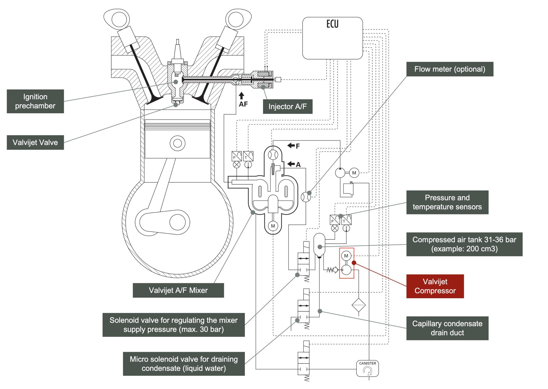
In this diagram, a small compressed-air reservoir (e.g., 200 cm³) can be seen at the compressor outlet. The pressure in this reservoir is maintained between 31 and 36 bar: when the pressure drops below 31 bar, the compressor restarts; when it exceeds 36 bar, it stops. As much as possible, the compressor operates at its point of highest efficiency, in a zone where acoustic emissions are minimal. The compressor is equipped with tight, low-reactivity check valves at the outlet of each stage, which helps maintain pressure between restarts.
A solenoid valve at the reservoir outlet regulates the supply pressure to the mixer: 5 bar during a −35 °C cold start, gradually rising to 30 bar when the engine is warm.
The variation of pressure and temperature in the reservoir at each compressor revolution makes it possible to characterize its volumetric efficiency when the pilot-charge A/F injectors are not operating: during fuel cut-off on deceleration, or when the engine is stopped (start & stop function).
The variation of pressure and temperature in the compressed-air reservoir also makes it possible to characterize the injectors’ effective flow rate as a function of needle lift, measured by their position sensor. When the compressor is stopped, the drop in pressure and temperature in the reservoir directly corresponds to the compressed-air consumption of the downstream system.
This strategy eliminates the need for a physical flowmeter: an accurate knowledge of the compressor’s volumetric efficiency as a function of inlet and outlet pressures allows its flow rate to be deduced. Likewise, a good characterization of injector flow rate as a function of needle lift allows their consumption to be quantified. By combining these two datasets, the flow rate through the mixer can be determined, including when both the compressor and the injectors are operating simultaneously.
A capillary tube allows condensation water to be drained from the reservoir: a micro-solenoid valve opens and produces a slow pressure drop, indicating that water is being expelled. A rapid pressure drop indicates that the reservoir is dry, and the micro-solenoid valve closes.
The characterizations of compressor volumetric efficiency and injector flow rate are ideally performed after condensate purge.